for In Rush Current Limitation, General Use

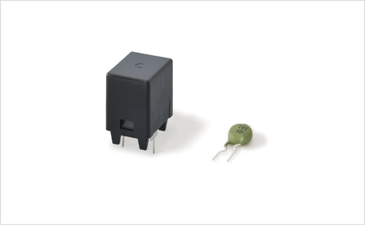
Case type and lead type
Superior to the competition in durability and space efficiency
Highly durable case type and Space-efficient lead type
Two types for in-rush current limitation
Specifications
- Rated Voltage :
- 100 to 240V
- Resistance :
- 15 to 100Ω
Resistance value changes at rated voltage
How they work
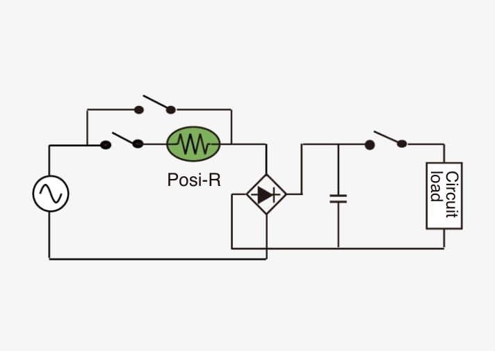
In-rush current limitation requires a high level of reliability. In these applications, the Posi-R is used in switch parts and parallel connection. When the power circuit is turned on and in-rush current is applied to the Posi-R, this current is quickly contained, thus protecting the secondary electronic equipment. Even during irregularities of continuous application of voltage, the Posi-R provides stability and safety by ensuring a constant temperature.
【Voltage application time and product temperature】
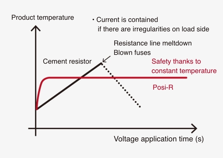
Compared to cement resistors, will not rise in temperature even under continuous current ow.
【Example of circuits used in】
Record on the market
Posi-R is used in lighting product power circuits, which are frequently turned on and off. Posi-R has one of the highest shares* in the Japanese market for thermistors for air conditioner power circuits.
- As of April 2017; according to Nichicon
Features
- Unlike cement resistors, these thermistors will not melt or short even when voltage is continuously applied after a switch part breaks down.
- Space efficient
- Because the thermistors have recovery properties, they can withstand continuous use.
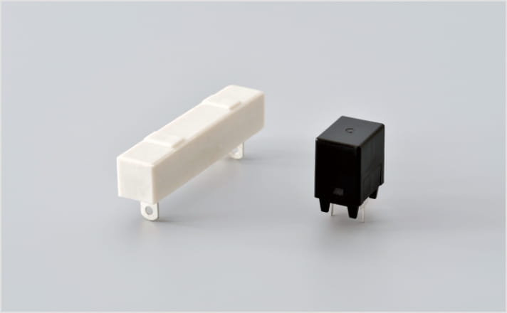
More space efficient than cement resistors
Applications
- Indoor and outdoor units Applications for commercial air conditioners
- Indoor and outdoor units for room air conditioners
- Lighting products for offices
- EcoCute systems
- Switching power supplies

Type No.
Case type
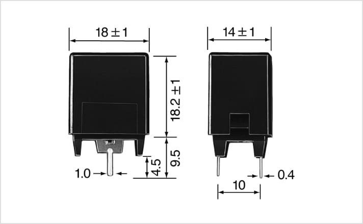
( Unit : mm)
| Type No. | Initial Resistance (at 25℃) |
Max.Operating Voltage ( Vrms ) |
|---|---|---|
| ZPM0RCH330A250 | 33Ω±25% | 276 |
| ZPR0RCH400A250 | 40Ω±25% | |
| ZPR0RCH660A250 | 66Ω±25% | |
| ZPR0RCH750A250 | 75Ω±25% | |
| ZPR0RCE820A250 | 82Ω±25% | |
| ZPR0RCE101A250 | 100Ω±25% |
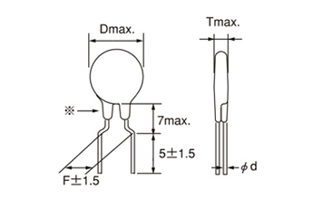
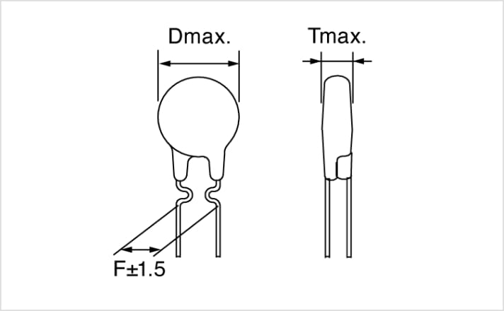
Lead type
| Type No. | Initial Resistance (at 25℃) |
Max.Operating Voltage ( Vrms ) |
Dimensions (mm) | |||
|---|---|---|---|---|---|---|
| D | T | F | d | |||
| ZPC54CH121 | 120Ω±25% | 276 | 7.8 | 6 | 5.0 | 0.5 |
| ZPC54CH181 | 180Ω±25% | 7.8 | 6 | 5.0 | 0.5 | |
| ZPC5JCG121 | 120Ω±25% | 15 | 6 | 10.0 | 0.6 | |
-
For inquiries such as product number selection, please contact your local sales staff
along with the required specifications, annual planning quantity, etc.
Application Guidelines
Application Guidelines of Positive Thermistors “Posi-R ”
General Observations
- Do not use”Posi-R” in the presence of oil or water.The parts could fail.
- Do not apply voltage in excess of the maximum operating voltage.
This could cause a short circuit or burn out. - Do not use “Posi-R” with reactive gas, reducing gas, or oxygen-free environment-electrical characteristics may deteriorate or burn-out may occur.
Notes on Usage
- Please use the parts within the rated operating temperatures according to the catalog.
- Please use at maximum operating voltage as specified in the catalog.
- The surface temperature during operation of “Posi-R” is 100 to 160˚C. Please take into consideration the effect of generated heat around the “Posi-R”
- Excessive press or shock (ex. drop) should not be applied to the “Posi-R”.
- Do not apply more lead stress than specified.
- Do not allow flux to come in contact with “Posi- R”, it may cause failure.
- The outer resin on the leads may be partially peeled off. This will not affect the function of products.
- In case of gluing “Posi-R”, the outer resin may be come off, please contact us in this case.
Notes on Storage
-
Packaged parts should be stored under the following conditions :
temperature : –10 to +40˚C
humidity :85% or less -
Storage of “Posi-R” devices may result in increased resistive characteristics.
They will return to the initial value by applying max. operating voltage prior to using the parts. - Shall be used shortly after opening the package. The prolonged exposure to the air may case to deteriorate the solderability.
Lead Shape
Bulk
( Unit : mm)
Taping

| Item | Symbol | Dimensions (mm) | Note | |||
|---|---|---|---|---|---|---|
| Nominal | Tolerance | |||||
| Diameter | D | Less φ12 |
Above φ12 |
- | Subject to part DWG | |
| Thickness | T | - | - | - | Subject to part DWG | |
| Lead dia | d | - | - | - | Subject to part DWG | |
| Pitch of component | P | 12.7 | 25.4 | ±1.0 | ||
| Feed hole pitch | P0 | 12.7 | 25.4 | ±0.3 | ||
| Hole center to lead | P1 | 3.85 | 7.7 | ±0.7 | ||
| Feed hole center to component center | P2 | 6.35 | 12.7 | ±1.3 | ||
| Lead to lead distance | F | 5.0 | 10.0 | +0.8 -0.2 |
±0.8 | |
| Tilt of component | ⊿h | 0 | ±2.0 | |||
| Tape width | W | 18.0 | +1.0 -0.5 |
|||
| Hold down tape width | W0 | 12.5 | min. | |||
| Slip out of hole | W1 | 9.0 | +0.75 -0.5 |
|||
| Slip out of hole down tape | W2 | 3.0 | max. | |||
| Height of component from tape center | H | - | - | Subject to part DWG | ||
| Lead wire clinch height | H0 | 16.0 | ±0.5 | |||
| Length of cut lead | ℓ | 1.0 | max. | |||
| Feed hole diameter | φD0 | 4.0 | ±0.2 | |||
| Total tape thickness | t | 0.6 | ±0.3 | |||
| Cut length of rejected component | L | 11.0 | max. | |||
Taping specification packaging example
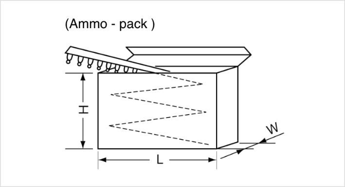
| Symbol | Dimension (mm) |
|---|---|
| H | 230 |
| L | 330 |
| W | 50,60 |