Characteristics of Positive Thermistors “Posi-R”
Switching Temperature (Resistance Anomaly Point)
At the resistance / temperature characteristics of positive thermistors “Posi-R”, the temperature which the resistance value becomes twice as high as that of at 25˚C, is called as “switching temperature” (Curie point) Thermistors “Posi-R” show anomalous temperature characteristics of resistivity, and typical characteristics are represented in Fig. 1. Optimum characteristics can be selected for each application.
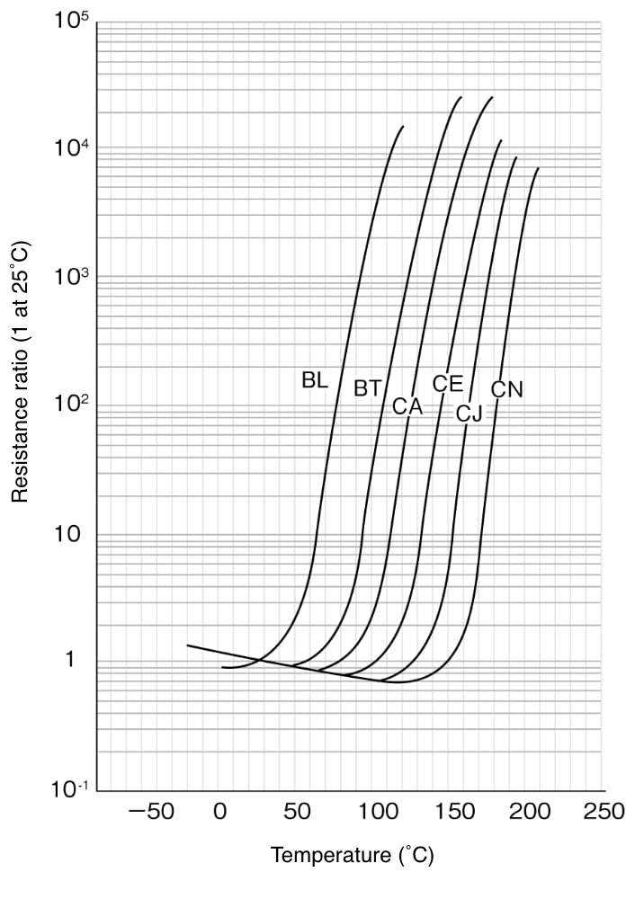
Fig. 1 Resistance / Temperature Characteristics
Temperature Coefficient
The temperature coefficient is calculated from the linear range at the steepest portion of resistance (T1 to T2) as illustrated in Fig. 2.

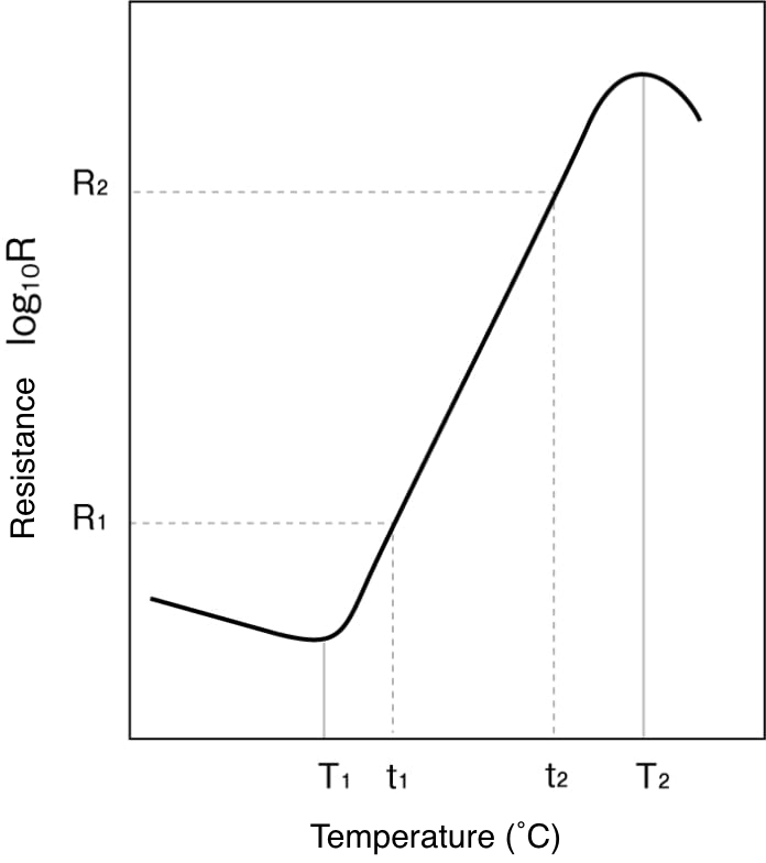
Fig. 2 Temperature Characteristics of “Posi-R”
Maximum inrush current
This is the maximum current (rms value) that you can apply without causing damage. If you apply current that exceeds it, you may cause damage.
Recovery time
This is a time constant that indicates the recovery characteristics after Posi-R action. The time it takes to switch the Curie point (twice the resistance of the initial value) after the switch is turned off.
Heat dissipation coefficient
When power is applied to the Posi-R and thermal equilibrium is reached, the following equation holds true.
V・Ⅰ=C(T1 − T0)
- V
- Applied voltage (V)
- I
- Equilibrium point current (A)
- C
- Heat dissipation coefficient (W/℃)
- T1
- Equilibrium point temperature of Posi-R (℃)
- T0
- Ambient temperature (℃)
If the heat dissipation coefficient is known, the equilibrium temperature point can be determined by substituting an arbitrary voltage and current into the voltage-current characteristics graph. Additionally, the increase in temperature (T1 − T0) when voltage V is applied to Posi-R can also be easily obtained.
Voltage / Current Characteristics
In the Fig. 3 circuit, the relationship between voltage and current is called as the voltage/current characteristics when the voltage is applied to Posi-R and it gets the thermal equilibrium.
As seen in Fig. 4, the characteristic follows Ohm’s law up to E1 point. The current increases when the voltage is raised, provided that the temperature characteristics is within the range of switching temperature or lower. The range between E1 and E2 is over the switching temperature but within the constant range of power dissipation.
However, beyond E2 point, an excess power will run and Posi-R will result in breakdown, accordingly. Therefore, the operating voltage of Posi-R shall be lower than E2.
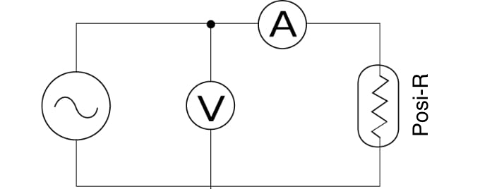
Fig. 3 Measuring Circuit
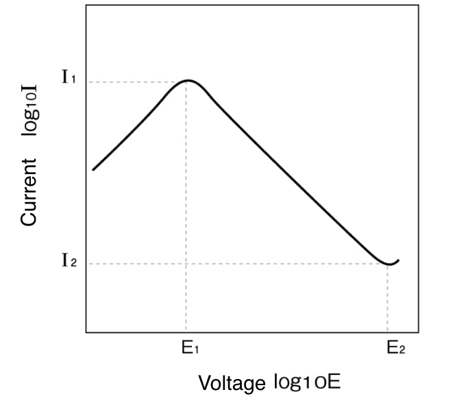
Fig. 4 Voltage / Current Characteristics
Equilibrium point current, equilibrium point resistance
When an arbitrary voltage is applied to the Posi-R and it is thermally stabilized (approximately 30 seconds or more), the current at that time is called the equilibrium point current. The resistance value obtained by dividing the applied voltage by the equilibrium point current is called the equilibrium point resistance.
Current , Time Characteristics
In the Fig. 5 circuit, when a load resistance (R) and a Posi-R are connected in series and an arbitrary voltage higher than E1 in Fig. 4 is applied, the Posi-R will have inherent temperature due to a current flowing through it. Its temperature rises as time passes by, and it exceeds the switching temperature in a certain time, resulting in a rapid damp of the current. The trip time can be adjusted by the current volume as shown in Fig. 6. By making use of these characteristics, a Posi-R can be used for the following applications;
- Timing circuit
- Switching use for motor starting
- Overcurrent protection
When the parameters of I1, t1, I2 and t2 in Fig. 6 are expressed in a logarithmic graph in the manner of Fig. 7, an almost linear graph is formed and the relationship between the circuit current and the trip time can be obtained.
But, when a Posi-R is used for a timing application such as a timer, the voltage shall be appropriately applied for 30 seconds or less as the changes of conditions may affect much more as time passes by.
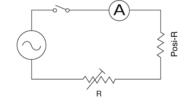
Fig. 5 Measuring Circuit
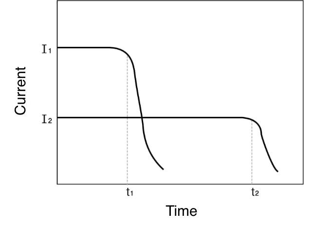
Fig. 6 Current / Time Characteristics
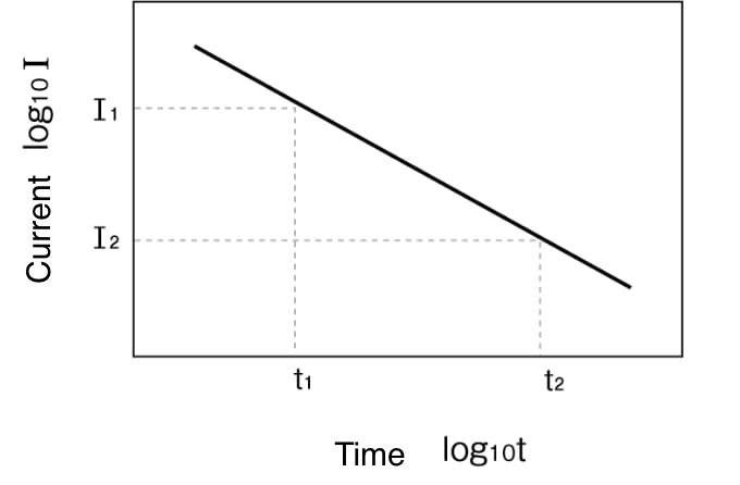
Fig. 7 Current / Time Characteristics