for Overcurrent Protection

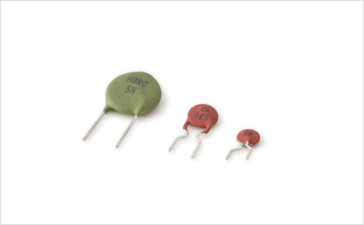
Hard at work in small automobile motors,
positive thermistors bring comfort to passengers.
Protects the motors in door locks, power windows and other small motors used in automotive applications.
Specifications
- Rated Voltage :
- 12 to 220V
- Resistance :
- 0.3 to 1kΩ
Resistance value changes at rated voltage
How it works
The Posi-R for overcurrent protection must be able to withstand repeated operation. The Posi-R controls the element and thus contains the current. As a result the current can be contained repeatedly after the current value returns to normal. The Posi-R is thus superior to fuses and polymer-based PTC’s. A fuse will “blow” when exposed to irregular current and is no longer useful. Polymer-based PTC, will change usage conditions the more it is used.
【Current–Time properties】
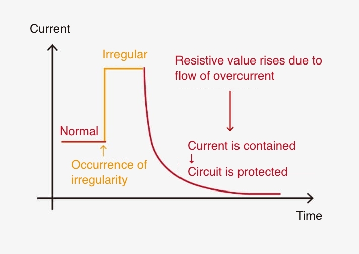
Current is contained in case of irregularity and circuit is thus protected.
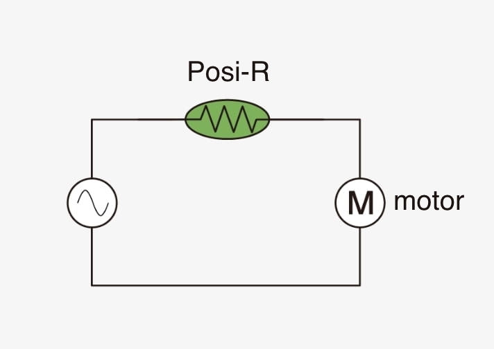
【Example of circuits used in】
Record on the market
Posi-R is mainly used to protect small motors for in-vehicle applications (door mirrors, door locks, etc.), where products must withstand repeated use; and in air conditioner circuits (inverter control circuit boards, outdoor unit fan motors, etc.).
Features
- Ability to withstand repeated use means there’s no need to replace it like with fuses.
- Offers superior repeated use since it’s non contact.
- Usage conditions won’t change even after repeated usage.
- No faulty operation due to noise.
Applications
- Door locks
- Door mirrors
- Vacuum cleaner power brushes
- Telephones
- Air conditioners
- Car audio systems

Type No.
| Rated Voltage | Initial Resistance ( at 25℃) |
max. Operating Voltage ( V ) |
Current Characteristic (mA) | |
|---|---|---|---|---|
| Normal Current (60℃) |
Limiting Current ( -10℃) |
|||
| 12V class | 0.3 to 2.2 | 16 | ≦ 300 to ≦1030 | 760 ≦ to 2580 ≦ |
| 25V class | 2.2 to 8.2 | 35 | ≦ 120 to ≦ 400 | 310 ≦ to 1020 ≦ |
| 50V class | 3.6 to 15 | 60 | ≦ 130 to ≦ 310 | 320 ≦ to 790 ≦ |
| 120, 220V class | 10 to 30 | 140 | ≦ 100 to ≦ 210 | 250 ≦ to 540 ≦ |
| 27~39 | 265 | ≦ 70 to ≦ 140 | 180 ≦ to 350 ≦ | |
Resistance and current values not listed in the catalog may be available.
Please contact your local authorized distributor with the required specifications and annual usage quantity.
Application Manual

When something abnormal occurs at the load such as a transistor circuit or a small-type motor, an abnormal current rushes into the power source circuit. Then, a power transistor at the transformer or the switching power supply generates heat in an abnormal level and causes breakdown. If a Posi-R for overcurrent protection is used in such a circuit, it can make the temperature compensation and protection for the power source and the load. An example is as shown in Fig.above.
As to the temperature protection, it can be perfectly made in use of this Posi-R owing to the excellent characteristics of resistance anomaly, that is, a current is reduced by the increased resistance due to the selfheating of Posi-R. At the current/voltage characteristics in Fig.2, there is a peak current. If a current larger than this peak current flows, a Posi-R acts. But if a current less than the peak current flows, a Posi-R does not act. The peak current varies depending upon the size of Posi-R, resistance and ambient temperature. Fig.1 shows an example of current characteristics.
At the current higher than the upper limit of fluctuation range, a Posi-R acts. Contrary, at the current less than the lower limit, it does not act. But the fluctuation range varies owing to ambient temperature. For instance, if the operating temperature range is supposed to be at –10 to +60˚C, the lower limit at +60˚C becomes the maximum value for a normal current (non-acting) and the upper limit at –10˚C becomes the minimum value for a limiting current (acting), respectively. Judging from the above explained relations, a Posi-R can be suited for the circuit where the ratio of a limiting current to a normal current is more than 2.5 to 3 times.
Characteristic Example
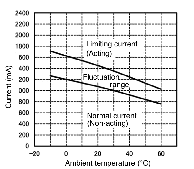
Fig. 1 Current Characteristics
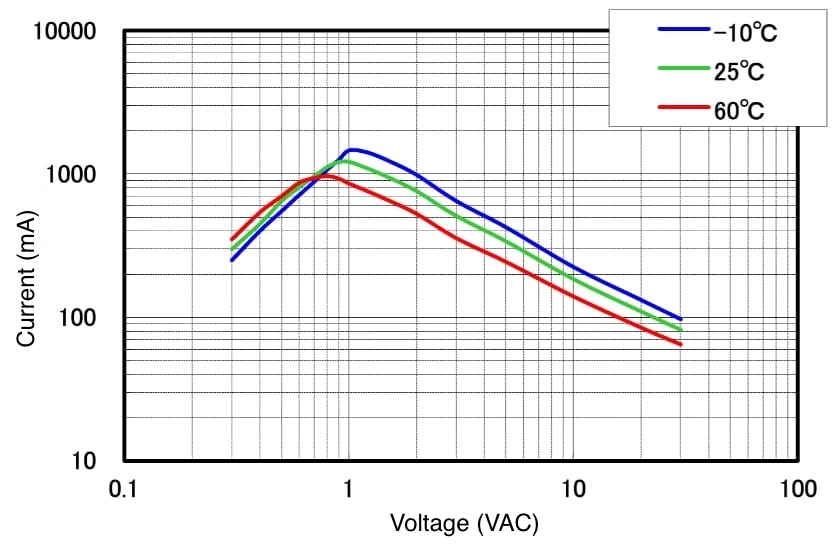
Fig. 2 Current / Voltage Characteristics
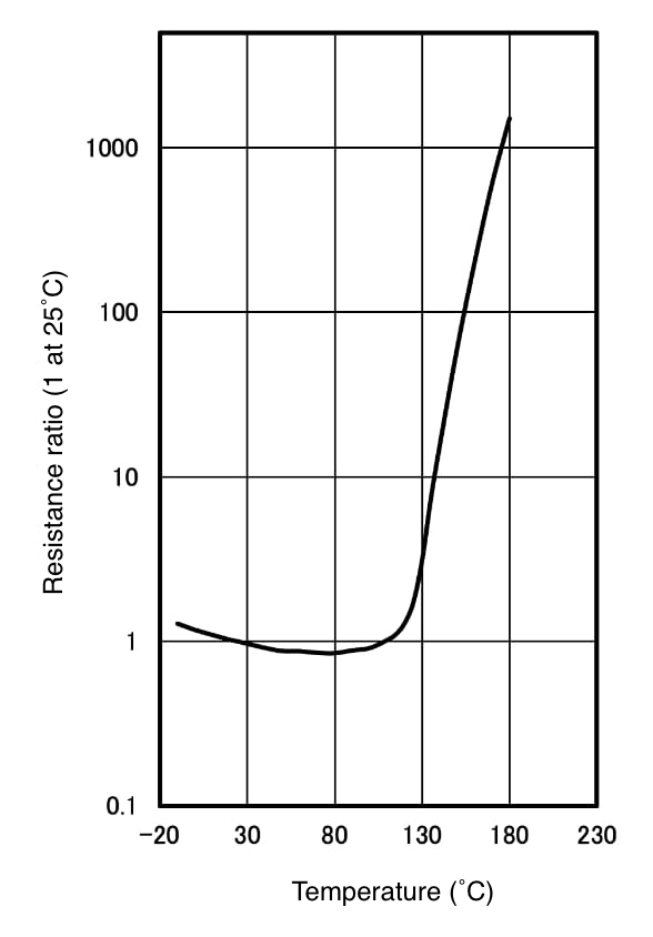
Fig. 3 Resistance / Temperature Characteristics
Application Guidelines
Application Guidelines of Positive Thermistors “Posi-R ”
General Observations
- Do not use”Posi-R” in the presence of oil or water.The parts could fail.
- Do not apply voltage in excess of the maximum operating voltage.
This could cause a short circuit or burn out. - Do not use “Posi-R” with reactive gas, reducing gas, or oxygen-free environment-electrical characteristics may deteriorate or burn-out may occur.
Notes on Usage
- Please use the parts within the rated operating temperatures according to the catalog.
- Please use at maximum operating voltage as specified in the catalog.
-
The surface temperatures for the "Posi-R" during operation are:
for overcurrent protection 100 to 160˚C .
Please take into consideration the effect of generated heat around the "Posi-R" - Excessive press or shock (ex. drop) should not be applied to the “Posi-R”.
- Do not apply more lead stress than specified.
- Do not allow flux to come in contact with “Posi- R”, it may cause failure.
- The outer resin on the leads may be partially peeled off. This will not affect the function of products.
- In case of gluing “Posi-R”, the outer resin may be come off, please contact us in this case.
Notes on Storage
-
Packaged parts should be stored under the following conditions :
temperature : –10 to +40˚C
humidity :85% or less -
Storage of “Posi-R” devices may result in increased resistive characteristics.
They will return to the initial value by applying max. operating voltage prior to using the parts. - Shall be used shortly after opening the package. The prolonged exposure to the air may case to deteriorate the solderability.
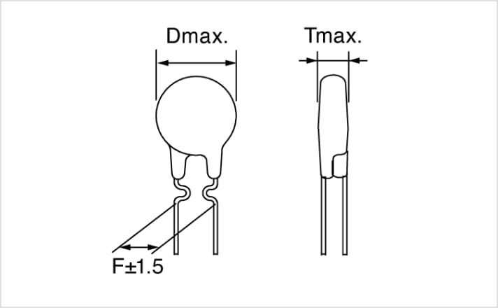
Lead Shape
Bulk

( Unit : mm)
Taping

| Item | Symbol | Dimensions (mm) | Note | |
|---|---|---|---|---|
| Nominal | Tolerance | |||
| Diameter | D | Less φ12 | - | Subject to part DWG |
| Thickness | T | - | - | Subject to part DWG |
| Lead dia | d | - | - | Subject to part DWG |
| Pitch of component | P | 12.7 | ±1.0 | |
| Feed hole pitch | P0 | 12.7 | ±0.3 | |
| Hole center to lead | P1 | 3.85 | ±0.7 | |
| Feed hole center to component center | P2 | 6.35 | ±1.3 | |
| Lead to lead distance | F | 5.0 | +0.8 -0.2 |
|
| Tilt of component | ⊿h | 0 | ±2.0 | |
| Tape width | W | 18.0 | +1.0 -0.5 |
|
| Hold down tape width | W0 | 12.5 | min. | |
| Slip out of hole | W1 | 9.0 | +0.75 -0.5 |
|
| Slip out of hole down tape | W2 | 3.0 | max. | |
| Height of component from tape center | H | - | - | Subject to part DWG |
| Lead wire clinch height | H0 | 16.0 | ±0.5 | |
| Length of cut lead | ℓ | 1.0 | max. | |
| Feed hole diameter | φD0 | 4.0 | ±0.2 | |
| Total tape thickness | t | 0.6 | ±0.3 | |
| Cut length of rejected component | L | 11.0 | max. | |
Taping specification packaging example
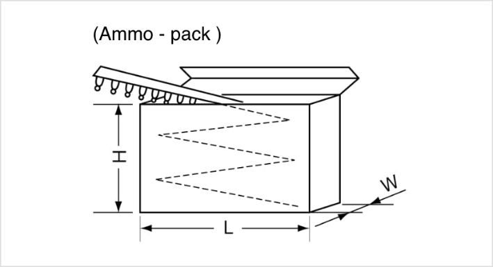
| Symbol | Dimension (mm) |
|---|---|
| H | 230 |
| L | 330 |
| W | 50 |